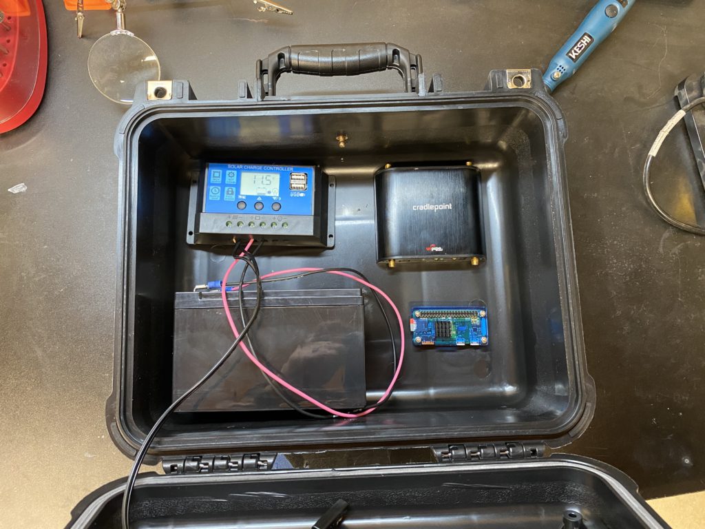
It was an interesting weekend. I got a couple things in the mail so I could finally start doing more prototyping. First off I received the cradlepoint device, so I mocked up what the enclosure might look like.
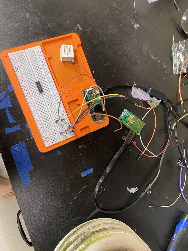
So that was nice. I also pulled my VP2 off my pole in the backyard to start prototyping with it’s sensors. That did not go well.
First was the rain gauge. This actually did go well. First I tried to follow the instructions here: https://projects.raspberrypi.org/en/projects/build-your-own-weather-station/8 which really was not super accurate and the code was hard to follow. So I started from scratch and read up on the gpiozero “Button” module. Once I figured out which wires did what on the Rain Gauge (I found that Red needed to be Ground, and Green worked for recording the tips. Green was on GPIO6). Now this may not seem like a big accomplishment but up until this point, my experience with GPIO on RPi has been just reading tutorials and copy/pasting stuff. So I figured this all out from scratch so I consider it a learning experience. So now I can count tips. Granted, the code is very simplistic right now and does nothing for rain. But I know how it works and I have a working snippet, so now I can figure out how to actually document rain.
Whoopsie Daisy
This is where the mistakes were made. The temp/humidity sensor. I could not find any solid documentation online about these sensors regarding usage with Arduino or Pi. It also seems Sensiron makes a couple different versions, the most popular being an I2C version. I was not sure what version the VP2 used, so I tried hooking it up via I2C and i found this page (http://www.pibits.net/code/raspberry-pi-sht31-sensor-example.php#codesyntax_1) that I thought would work. Well as i’m finding out, the Davis colors don’t always match the standard colors, and things may be miswired. How did I find this out? Well I know I don’t have Covid-19 because I could smell something very burny. Uh oh.

So I took the little filter off the top of the sensor, and it was hot to the touch. Very hot. I unplugged it, but realized at that point i’ve probably fried the sensor. Whooooops.
So yea. At this point i’ve managed to fry the standard Davis sensor. But that may be a blessing in disguise.
SHT31. Destroyer of obs?
After some googling, I find out that the SHT31 is not exactly the most accurate sensor, especially in the Davis units:
http://www.wxforum.net/index.php?topic=36204.0
https://www.wxforum.net/index.php?topic=34658.525
So from what I can tell, the SHT31 that Davis uses is not super accurate. Nor does it use I2C, or even an analog signal. I found this page that describes that the SHT31 uses “Legacy Sensirion Sensibus” or “LSS”. I’ve not found any good documentation online about using this with an RPi or Arduino. So if i’ve already caused myself one problem, I might as well fix it. I’m also trying to fix the reception issue, so I might as well fix the accuracy issue as well. This will make the idea of the system being completely plug and play null. HOWEVER I feel like most ppl that care enough about the accuracy of their station and want to completely convert over to a Pi based system will be keen on replacing the problematic SHT31 so I don’t see it as a big problem.
The Pressure is on…. the same board!
So with that, I opted to get an SHT35 sensor. They come in a few forms, but almost all are shipping from China right now and it’s almost a month wait. But I was able to find this one on Amazon for a good price. Funny enough buying from the manufacturers website ends up taking much longer for shipping. This will be here in a few days. The SHT35 not only has better accuracy, but is I2C. What else is I2C? The BMP180! That will make things easy. One of the big problems is that the pressure sensor is in the Console or Envoy unit. So the plan is to have the BMP and the SHT on the same board in the radiation shield, and use I2C to have them use the same RJ11 cable. Problem Solved! Problem Solved! We solved the problem, problem solved (That’s also from Peg + Cat). So I should know by the end of week if that will work. The other issue is the size of the board.
The non-fan aspirated shield mounts the sensor like this:

That means size wouldn’t really be an issue for that board. But the fan aspirated version (which is what I have at the station i’m upgrading, and i’m not able to find a good pic of) the sensor unit actually slides down into the shield in two “grooves” and so size is important. It’s the same exact sensor, just different mounting. So with that in mind I need to make sure I adhere to the same size. Ultimately my goal is to create a PCB for this as well, so if someone else wants to use the VP2 with an Arduino/Pi directly they can and replace the sensor.
So with that, my next goal is wind sensors. This will also introduce me to analog inputs, as the wind vane is a potentiometer. So while I wait for my temp/humidity parts, I can get cracking on wind speed.