Setting up WeeWX with AWS IoT Core

Introduction

Ever since I started playing with weather stations over 10 years ago, i’ve always been fascinated by the software that runs them. I started years back with WView, which was C based and really not all that well optimized but man was it stable! Then when it stopped development, I migrated to WeeWX which has been an absolute godsend for running my stations. Not only is it built in Python so easy for me to understand what it’s doing, but it also has a huge community around it with plugins for just about data source/destination you could think of.

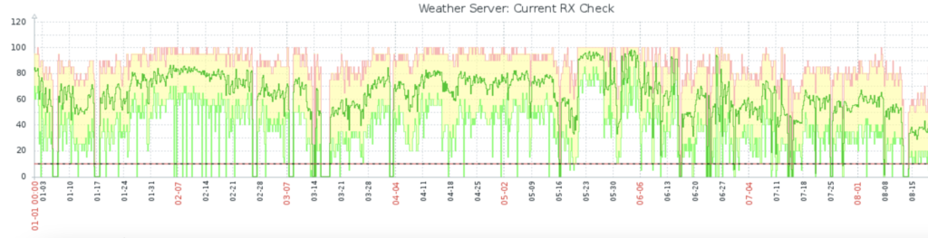
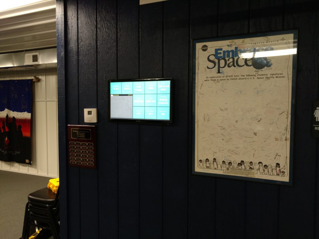
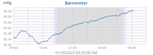
While WeeWX is great, it does leave a bit to be desired sometimes. For example, these are some of the stock visualizations that come with it.

But what if you wanted something else? Something that maybe you are already using? What about something like Grafana?

Chances are if you are already using Grafana, you are probably running it locally with something like Home Assistant also piping into it. But what if you aren’t? What if you want something cloud based where you can also modify cloud resources, or other business metrics as well as weather data? If so, this blog is for you and you should read on.

Setting up the Prereqs in WeeWX

First off, i’m doing this on a Raspberry Pi (Buster 10) running WeeWX 4.8.0. Your configuration may vary of course, but I tested it on another setup running the latest Ubuntu on an EC2 instance and the latest WeeWX and it seemed to work fine.

We will be using this plugin for WeeWX: https://github.com/matthewwall/weewx-mqtt

Get started by setting up the downloading the package and running the installer. This will modify the weewx.conf file with a basic configuration.

Setting up the Prereqs in AWS

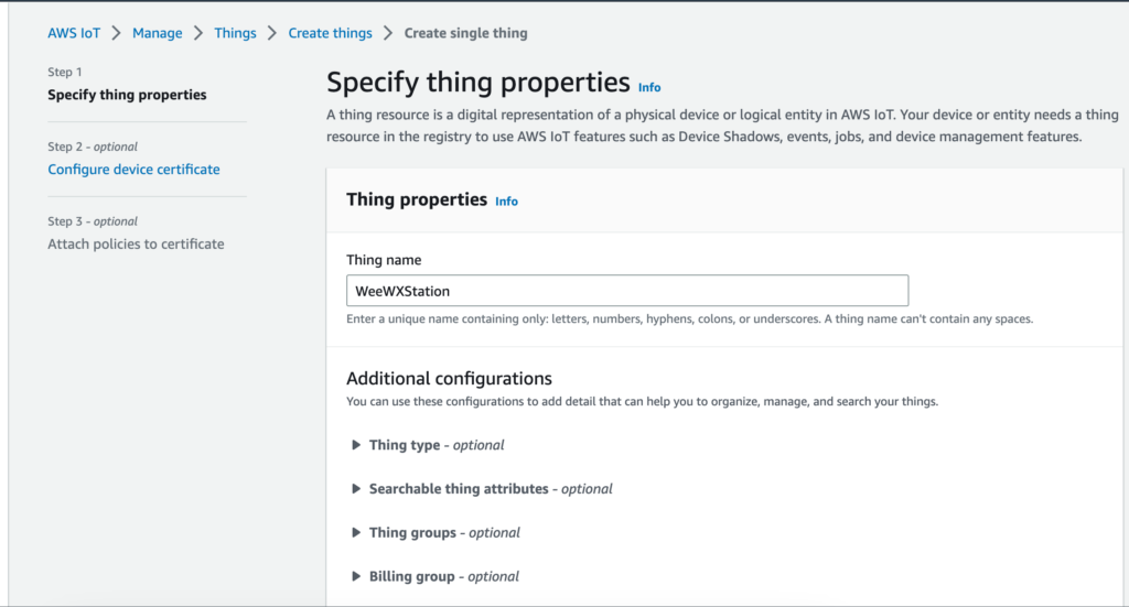
First we’ll navigate over to the IoT Core Console and Create a new thing.

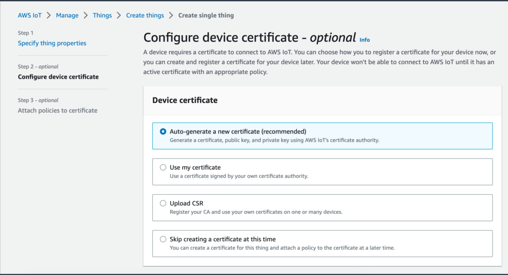
Now we’ll Configure the certificate. We’ll have IoT Core set up the cert for us.

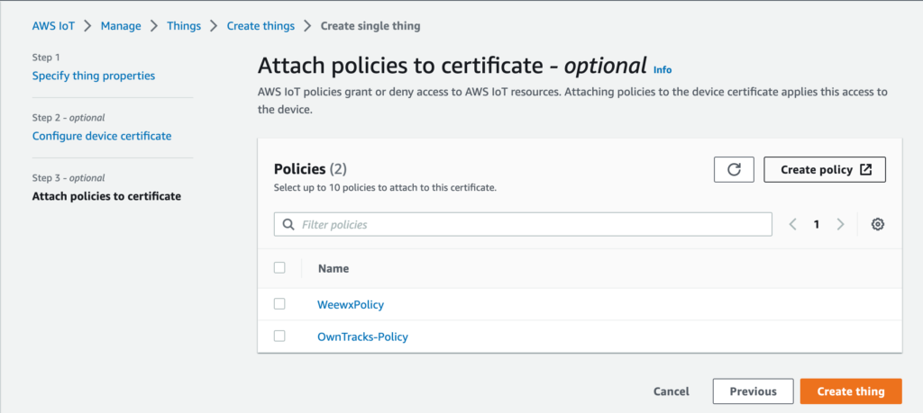
Now we’ll create our policy. The policy will dictate what devices can connect to IoT Core and what topics they can send to. Let’s do “Create policy”

Configure the new policy with the following json, of course replacing <account> with your account number:

{
  "Version": "2012-10-17",
  "Statement": [
    {
      "Effect": "Allow",
      "Action": "iot:Connect",
      "Resource": "arn:aws:iot:us-east-1:<account>:client/weewx_*"
    },
    {
      "Effect": "Allow",
      "Action": "iot:Publish",
      "Resource": "arn:aws:iot:us-east-1:<account>:topic/weather*"
    }
  ]
}

Now you can create the Thing, and download the certificates. We need the device cert, the private key, and the root ca. You also need to download the public key, but we won’t be using it.

Once you’ve downloaded the certs you can click “Done” and we are finally ready to configure our WeeWX config.

Finally before we leave the AWS Console, go to the IoT Core Console, navigate to “Settings” and grab the “Device data endpoint” which is the URL we’ll be using with WeeWX that tells us where to send our data.

Setting up WeeWX with certs

Back on our WeeWX instance, let’s create a folder for our certs. I created this in /etc/weewx/certs to make it easier for the conf file to read it. Now we’ll create the files. This is what I named my files. You can name them whatever you want as long as it’s consistent with your weewx.conf file. Once the files are created, copy/paste the contents of each of your cert files into the appropriate file.

root@PiAware:/etc/weewx/certs# ls -alh
total 20K
drwxr-xr-x  2 root root 4.0K Jan 31 19:53 .
drwxr-xr-x 11 root root 4.0K Jan 29 18:35 ..
-rw-r--r--  1 root root 1.2K Jan 29 18:29 cert.crt
-rw-r--r--  1 root root 1.7K Jan 29 18:28 private.key
-rw-r--r--  1 root root 1.2K Aug  8 19:29 rootca.pem

Now we’ll update the weewx.conf file. It’s a pretty simple config

    [[MQTT]]
        server_url = mqtts://<endpoint url>:8883/
        topic = weather
	aggregation = aggregate
	[[[tls]]]
		ca_certs = /etc/weewx/certs/rootca.pem
		keyfile = /etc/weewx/certs/private.key
		certfile = /etc/weewx/certs/cert.crt

Once this is done, you can restart weewx and verify messages are getting through.

Verifying data flow

Navigate back to AWS IoT Core console, and open up “MQTT test client” and subscribe to “weather” as the topic

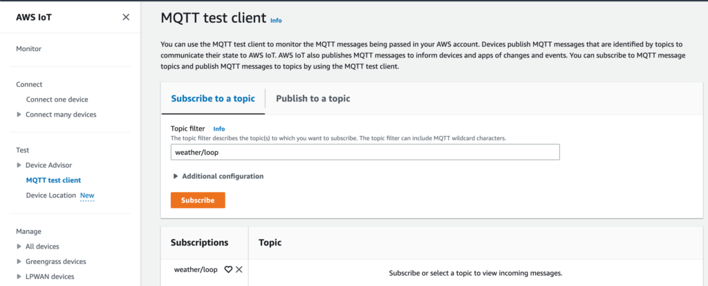
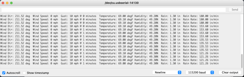
After a short time, you should see entries coming across. Here is an example of one of mine:

{
  "monthET": "0.0",
  "barometer_inHg": "30.417",
  "outHumidity": "63.0",
  "inDewpoint_F": "22.4014329174",
  "windGust_mph": "0.0",
  "dayET": "0.0",
  "interval_minute": "1.0",
  "highOutTemp_F": "17.4",
  "dewpoint_F": "6.8950371838",
  "consBatteryVoltage_volt": "0.89",
  "wind_samples": "20.0",
  "rain_in": "0.0",
  "insideAlarm": "0.0",
  "lowOutTemp_F": "17.3",
  "sunrise": "1675171500.0",
  "hourRain_in": "0.0",
  "cloudbase_foot": "3302.76427641",
  "heatindex_F": "17.3",
  "outsideAlarm1": "0.0",
  "soilLeafAlarm2": "0.0",
  "outsideAlarm2": "0.0",
  "altimeter_inHg": "30.3231865786",
  "forecastRule": "9.0",
  "dayRain_in": "0.0",
  "rainAlarm": "0.0",
  "windrun_mile": "0.0",
  "yearRain_in": "2.16",
  "outTemp_F": "17.3",
  "stormRain_in": "0.0",
  "windchill_F": "17.3",
  "inHumidity": "19.0",
  "extraAlarm1": "0.0",
  "extraAlarm2": "0.0",
  "extraAlarm3": "0.0",
  "extraAlarm4": "0.0",
  "extraAlarm5": "0.0",
  "extraAlarm6": "0.0",
  "extraAlarm7": "0.0",
  "extraAlarm8": "0.0",
  "humidex_F": "17.3",
  "appTemp_F": "11.3358263051",
  "rainRate_inch_per_hour": "0.0",
  "forecastIcon": "6.0",
  "rxCheckPercent": "85.4166666667",
  "soilLeafAlarm4": "0.0",
  "pressure_inHg": "29.3092238355",
  "inTemp_F": "65.8",
  "soilLeafAlarm3": "0.0",
  "usUnits": "1.0",
  "soilLeafAlarm1": "0.0",
  "leafWet4": "0.0",
  "ET_in": "0.0",
  "txBatteryStatus": "0.0",
  "yearET": "0.0",
  "windSpeed_mph": "0.0",
  "rain24_in": "0.0",
  "dateTime": "1675216860.0",
  "sunset": "1675208220.0",
  "windSpeed10_mph": "0.0",
  "monthRain_in": "2.16"
}

So now we have data coming into AWS IoT Core, what’s next? In the next blog post, we’ll look at how we can use Grafana to visualize our data from WeeWX

Davis Vantage Pro 2 Open Weather Station Part 9: Back in the saddle.

Man it’s been a while since i’ve done anything with my weather station. I honestly got kinda burned out by it as I was thinking about all the work ahead of me so I stopped working on it for a while. However, recently my “Production” station in my hometown started experiencing more issues that prompted my attention. I started to get more and more RX Check emails from Zabbix, and weirdly it coordinated with weather events. When a storm moved in, my station would drop.

Year so far in Zabbix of RX Check.

I’ve been getting sick of these drops. There doesn’t appear to be any reason for it. When I go out and test it, the solar panel works fine, and it typically works just fine over night. So is it a SuperCap issue? Panel? I have no clue. But the wireless setup has always given me issues at this location, however at my house, I’ve never had problems. So while the idea of replacing all the Davis Wireless is a great one, in the short term, it’s not really feasible.

Wireless isn’t the only option

It’s true! Davis makes a Cabled version of the VP2 that works exactly the same as the wireless, just over a long cable. I noticed on the VP2 board, there is a COMM port that looks just like the cabled. So I reached out on my local friendly wxforum and asked the question: https://www.wxforum.net/index.php?topic=42646.new#new. The inevitable occurred and I was told it couldn’t happen. BUT I did receive a reply asking about a trade. Sure enough, over about a 3 week period, I sent a guy in Canada my wireless console and ISS board from my home station, and he sent me his cabled console and ISS board. Now we’re talking! After reading around, it seems that the ISS sends data over RS422/RS485 and is encoded in a certain way. I found this post: https://www.wxforum.net/index.php?topic=32706.0 that even included a code sample! With this new info, I went to work.

Workbench testing

Using the wiring guidance and some trial and error, I got the wired console reporting via the Arduino code, but on an ESP32. I had to change the serial number, apparently my board won’t let me use UART1, so I had to use UART2 for the RS485 board I got on Amazon. With that, I was greeted with readings!

Readings via the Serial console of the Arduino IDE
Setup on the bench. RJ11 connector, RS485 board and ESP32 dev board.

So now that I have it reading, now I have to think about next steps. The nice thing is that the ISS Board does all the heavy lifting. Rain tips, wind speed/direction, etc. Those were all things I was gonna have to calculate with my Open Weather Station idea. So this skips a lot of steps.

New Plan!

Now that I know this works great, this changes how I plan to approach this, at least at my Production station. I want this to be low maintenance as possible. So my plan will be use an ESP32 board in an enclosure with battery, solar panel, and LTE Modem (CradlePoint) and use an ESP32 board with Ethernet. I have an Olimex EPS32-POE board that works awesome with MicroPython. I am planning on building this in MicroPython, because it’s what I know. So the next step is to take the Arduino code and understand what it is doing every step of the way, and translate that into Python. I also have to do other things, like monitor battery voltage on the ESP32 board, as well as monitor enclosure temp/humidity with a BME280. So there’s a few pieces to this puzzle.

Data collection

Have I mentioned how much I love WeeWX? I found a “Driver” for WeeWX that allows WeeWX to ingest data from an MQTT Topic. I deployed WeeWX on a small EC2 instance, and used AWS IoT Device Simulator to simulate a weather station uploading at the same rate as the Davis ISS (2.5 seconds) and it works great! WeeWX ingests the “loop” data that i’m sending and creates archive entries into a database. It also can take random messages so I can send battery voltage every minute in a separate MQTT message and it’ll ingest that. Neat! So this way all I have to run on the ESP32 is MQTT and whatever I need to pull data from the sensors and i’m good. Makes the ESP32 a much better choice for the edge device over a Pi Zero.

So what’s next for the Open Weather Station Idea? I’m still pursuing it. I’ll have a separate post in regards to my thoughts on that, but for right now, I’m focused solely on creating a more reliable “Production” station using multiple Davis OEM pieces.

Installing an “eBay Special” Snorkel on a Lexus GX470

When I lifted my 09 GX470 I knew I wanted to do some mild off roading and so far, it’s been great for that. But I decided I really liked the look of a Snorkel. For those not familiar, on the GX and many vehicles, the intake air comes from the inner fender. So the airbox has a tube that just opens into the fender, and that’s it. This can cause problems when crossing deep water, as it can suck in water, or even if hitting a deep puddle and lots of water sloshing up into the fender. Now the air box does have drains in it, but it’s possible to get enough water in that it hydrolocks your engine, which is not good. So the snorkel raises the height of your intake to roof level, which also helps in regards to dust. So anyway, there are multiple options ranging in prices. I opted for a popular choice which is known as the “eBay Special” that I picked up for about $130. Now this model is for the Prado 120, so you would think it should work, but not without some work.

This job is not for the faint of heart. If you aren’t comfortable cutting some bigass holes in your car, as well as cutting plastic and unbolting things, this is not the job for you. Anyway, onto the work.

Preparation Work

First off, remove the fender liner, and the wheel. I’ve seen tutorial videos and posts, and a lot of people don’t remove the wheel, which seems to just make things really difficult. So anyway, let’s start there. But first, hydration. Always make sure to keep water around, getting dehydrated is no fun:

Water!
Fender liner removed. You can see where you are going.
Airbox removed.

Once you remove the airbox, there are 3 10mm bolts (pretty short) holding the fender on, and then open up the passenger door, you’ll see a clip holding in a piece of fabric, pull that clip out, then you’ll find another 10mm bolt. These 4 bolts hold the fender on partially, and give you lots of wiggle room. Anyway, now you’re ready to get started on drilling.

Drilling the holes

The snorkel comes with a template. And it’s pretty decent, but it’s not perfect.

How it seems like it should line up.

With the template attached, it seems like you’re ready, but not so fast. I put the snorkel up and realized that it was too far back into the door area. I had to move it about 1/2″ forward, which seemed to line up much better.

How much I had to move it forward. Don’t take the template at face value.

So now once you have test fit, it’s time to drill. I used a step bit, and a 4″ hole saw. Pro-tip: Get a quality hole saw. Mine was part of some $10 kit from Menards or Harbor Freight, and it sucked. Once you have drilled it out, make sure to paint over the exposed metal. Amazingly, the previous owner had a container of OEM touch up paint with the GX and it was still good!

Holes drilled. Note I did have to drill out the holes a bit more (to the next “step” on the bit) to give some more wiggle room. But the big hole was perfect!

Snorkel adjustments

So next is to get the snorkel ready. It comes with threaded rods to insert into the threaded holes. So I sunk them down all the way in. Note, there is an allen head and a smooth end. Make sure the allen head is out, this will make things hella easier later.

Rods inserted. Remember how I said to put the allen head side out? Yea i didn’t realize that on a few.

So now your holes are drilled, and you can test fit. So i did. First problem. Virtually none of the rods actually cleared the fender enough on the inside to catch a nut with the washer. So i realized the threads were not far enough “out” so I used the allen heads to work the threaded rods out another 1/4″ or so. I ended up having to adjust one of them later, inside the fender, so the allen head came in handy and I was able to work it out a couple threads and get the nut to catch. Anyway, now that you’ve verified your holes are good, time for the next piece.

A-Pillar shenanigans

So the kit comes with a bracket with 4 rivets to secure the bracket to the a-pillar. I drilled two holes and realized the rivets were far too long to work in the small A-pillar

Showing how far the rivet stuck out. I suppose I could have pulled it a bit and got it to work, but I went a different direction.

So with the rivets being garbage, I found some sheet metal screws. I filled the holes I already drilled with silicone.

Bracket mounted up. 2 sheet metal screws, plus the old holes filled with silicone.

I put silicone under the bracket, and then screwed into it, then put more silicone on top to seal it up. I ended up putting a bead of silicone all around it to completely seal it up.

Internal Tubing

So now you have the piece connecting the snorkel to the airbox. You’ll have a heck of a time trying to shove it up there. once you do get it in the fender and out both holes, you’ll realize it sticks out way too much. If you put the rubber sleeve on it, you’ll find that it sticks out about an inch. So here comes the trimming:

Trimmed off the snorkel end. It’s pretty rough but I used a Multi-tool after this to smooth it out a bit.
The intake side. Trimmed down about 1/2″

I also trimmed about 1/2″ off the actual snorkel tube. I also trimmed about 1/2″ or so off the rubber sleeve. With all this trimming, i was able to get a perfect fit with the sleeve, and with some clever and uncomfortable wiggling I was able to mate the two together

The sleeve inside the fender with both clamps installed and tightened down. Not all the bolts are attached yet.

Nuts and Bolts

So now it’s time to actually attach things. The front bolt is pretty easy, as long as you can get a thread on it. The back two are also pretty straight forward. I had a heck of a time with the top bolt closest to the fender tube though. Because it was tilted down, I couldn’t get the washer to stick. So I used Super glue. I attached the nut to the washer using some super glue, and then threaded it on with my finger. Worked great! Then the wrench broke the super glue, and i was able to get it tightened down. However there was one that I just could not get to fit inside the fender. The top bolt closest to the passenger door just would not set into the fender. So i didn’t worry about tightening it. Once everything is tightened down, you’re ready for the intake step.

Intake connections

So for the airbox, it has a stock rubber hose piece, and it “clicks” onto the airbox. those little clips get in the way of the rubber sleeve. So i used a multi-tool to shave those pieces off. I did have to slice a small slit in the rubber sleeve to get it to fit completely. But once I did, i was able to again, using some uncomfortable manuevering, get the two mated up

Hard to see, but it’s all connected up.

Final results

It took me the better part of 4 hours to finish this up. I had done most of the fender liner removal, airbox removal and tire removal the night before so that helped out. Those stupid clips are horrible. But now i’m pretty happy with it!

I hope this helps anyone else who buys the eBay Special snorkel. It’s not an easy install but when it’s done it looks pretty darn good!

Davis Vantage Pro 2 Open Weather Station Part 8: Remote Management!

Currently with a Raspberry Pi setup, it’s pretty easy to remotely manage my station. I just SSH into that Pi. That does let me have some control over my station, as I can reboot the server, restart weeWX, etc. But with an ESP32, it’s not as simple as that. So I started looking and I discovered that the CradlePoint supports Out of Band Management in the form of serial redirection! However, per this document: https://customer.cradlepoint.com/s/article/Supported-USB-to-Serial-Adaptors-for-Out-of-Band-Management it requires a serial with an FTDI Chipset. The ESP32 dev board I have uses a CP210x which is not supported by Cradlepoint via the USB. But luckily, you don’t HAVE to use that port!

Using an FTDI cable with the Heltec ESP32 dev board.

With that setup, I could talk over FTDI to my board very easily, and it just took 4 connections! This particular cable is a 5v cable, but you can also get 3.3v setups as well. So what about the Cradlepoint? First, I enabled Serial Redirection (https://customer.cradlepoint.com/s/article/NCOS-Out-of-Band-Management) and then plugged that in. It was just that simple!

ESP32 board hooked up to the Cradlepoint
Logged into the CradlePoint (IBR600-8fe is the hostname) and then entering into the serial device. The first few lines of -0.03xxxxx is output from a Python script I have running on the ESP32 for an ultrasonic distance sensor. I then cancelled that script and had the Python prompt.

So yay! I have remote management and can see exactly what I would see if the ESP32 board was hooked up to my laptop. This means in the wild when this is deployed, I can easily log in and troubleshoot, even if the ESP32 itself loses connection. As long as the CradlePoint is up and running and online, I can access it.

Next on the project board is networking! I got a Lan8720 module to start working with. Yes the ESP32 has wifi but i’m wanting to do wired ethernet. So hopefully i’ll have that figured out soon.

Davis Vantage Pro 2 Open Weather Station Part 7: ESP32 vs Pi?

Since I visited the weather station last week, the speed at which i’ve been working on the project has definitely slowed. Except it hasn’t! I’ve been working on the software side. Now that I know all my sensors work with a Pi, i’ve been thinking about next steps. Currently i’m using WeeWX, and I love that software. The graphing is awesome, and so is the open-ness of it. So many plugins are available. However, given i’m trying to create a setup that uses very little data, WeeWX at the edge isn’t really ideal. Uploading all those graphs and relying on the edge device will really tax it and use up data. So really I need the Edge device to be absolutely as simple as possible, with WeeWX somewhere else.

So I started looking at MQTT options for WeeWX. Obviously i’m using MQTT since it’s the protocol of IoT. It’s incredibly reliable, and lightweight. I know there are options that send MQTT from WeeWX, but not the other way around. Until I found this! https://github.com/bellrichm/WeeWX-MQTTSubscribe which after a bit of setup works perfectly! I was able to create a Python script that creates random obs and send them to an MQTT topic in AWS IoT Core, which WeeWX hosted on EC2 would then receive. There are still some bugs to work out in regards to architecture, but I like what I see so far. So my plan will be to run WeeWX either in Docker via Fargate, or on a cheap EC2 instance (probably T4g using the Graviton2 instances) using something like EC2 Savings Plans or Reserved Instances. Should cost me about $5-7 a month. I’ll have a second post that goes into the WeeWX setup once I make up my mind on exact setups.

Speaking of making up my mind. I’ve done a lot of thinking regarding what will power this station. I’ve been talking a lot about Raspberry Pi, but I’ve started to think about other options. Recently, Raspberry Pi unveiled the “Pico”. a $4 ($2 at my local MicroCenter!) which is a Raspberry Pi produced Microcontroller. I started to think about revisiting the idea of using a MicroController. After all, I just said the Edge device should be as simple as possible. So I did some looking and reading, and I think I have my answer: The ESP32.

Not my first ESP rodeo

So full disclosure: This is not the first time i’ve used an ESP32. In fact, I have 3 on my workbench I bought months ago. When I started working on IoT with AWS I bought a couple to start learning about Microcontrollers. However this didn’t last long, as everything was in C/C++. I have never known C or even the essentials. And so my motivation to learn was there, but I always ended up getting really frustrated, and since I had no idea how C/C++ worked, troubleshooting was so hard. I went with the Pi for this project because it was familiar. It was Linux, it runs Python, etc. But then I learned about something life changing; MicroPython.

ESP32 Dev board. About the same size as a Pi Zero.

You can run Python on a Microcontroller! I started looking into MicroPython and did a few getting started guides. I was able to accomplish more in 20 minutes with MicroPython than I did in hours with C/C++ and the Arduino IDE. I was able to get the anemometer/wind speed working immediately with very little work so that was a great start. I’m thinking this may be the way to go.

It also is way better from a hardware perspective. It has 12 ADC built in pins. So that will reduce the number of external ADCs I have to include. It also sips power. The Pi Zero sips power too, but the ESP32 is on a whole other level. So it will last even longer on a battery/solar panel. The only downside is while it does include Wifi, I am using a wired connection. So I have ordered an ethernet breakout board that should work, and so i’ll update when I get that and see if it works.

Remote Management

One of the disadvantages of switching to an ESP32 vs a Pi is a change of management. With a Pi I can just SSH in and Bob’s your uncle. but with an ESP32, that’s not an option. However, I did learn that the CradlePoint apparently supports Serial redirection with the USB Port! You can actually SSH to the Cradlepoint unit and then connect to the serial port. However this requires a FTDI serial connection, and by default most ESP32 boards i’m finding use a CP201x from Silicon labs. I did buy a couple FTDI breakouts and am gonna see if that works. If it does i’ll be able to connect up just like I do from a laptop, but over the internet.

So I know this post was kinda rambly, but I really just wanted to get my thoughts down regarding the Pi vs Microcontroller setup. Having the ability to run Python on the ESP32 means there’s no reason to not use it. The Pi is an amazing device but when the device literally has one job: read input from about 20 sensors, less is more.

Davis Vantage Pro 2 Open Weather Station Part 6: Testing in Production

As Amazon added MLK Jr day as a corp holiday this year, I decided it would be a good day to do some testing on the station. And so I loaded up the car and headed west, to test the sensors that I do not have on my station at home. So that would be the Leaf wetness, soil moisture, soil temperature, UV, and Radiation. Now, really I didn’t *need* to do this, as based on the spec sheets, they should all function very similarly.

For example the UV and Radiation sensor both output a voltage. So it’s a three pin setup, piping that through the ADC provides a good value, just like the wind direction does. But I wanted to test that.

The soil temp/humidity sensors are resistive, and so I could really just use any resistive sensor. I tested it with a Photoresistor ahead of time to make sure.

My measure of success for each one was that the values were constant, and they were! It was quite cloudy, so i expected a low value for Radiation and UV, which I did see that. Soil moisture and temp i wasn’t really sure what value to expect, but again, the values were constant, which is about right for sensors buried in the ground.

Finally a good use for the GX470 side opening gate. I was able to park right up to the station and be close to all my hardware. Although this is the second attempt, the first attempt i managed to hit the station with the trailer hitch…
This is how I tested the UV/Radiation sensors. Lodged the pi base up under the enclosure and just hooked it all up. Worked quite well but had to be very careful as even the slightest movement would make it fall..
More of the testing setup. The Pi is connected to the network via a Cradlepoint. All of this plugged in to the 115v outlet in the GX470.

In terms of networking I also tested out the WAN on Wifi functionality of the CradlePoint. I used a Verizon Mifi from work and set it up on the Cradlepoint. From there I was able to connect ethernet to the PI via a USB Adapter and I had internet! So not only was I able to SSH into the Pi from my Macbook, I was also able to get internet on the Pi. I still need to test failover as the Cradlepoint does have a Straight Talk SIM card in it (That does work) so I need to verify if the Wifi drops, it will connect up to Verizon via Straight Talk.

Finally I’ve been thinking about layouts. Here is a photo of the whole station:

The most up to date photo of the station.

The sensor RJ11 cables from the main ISS board are way too small, and I’m not sure I want to extend a bunch of cables. Plus as I went through with the RJ11 previously, you gotta be careful with the wiring. So I think i’m gonna have a PCB for the Soil Sensor enclosure, and the main sensor pack. These will bolt up right where the existing Davis boards do, and will have RJ11 for the main pack, and for the soil moisture/temp board, have screw terminals since those are just two wire sensors. Plus an RJ11 for the leaf wetness.

For connecting I had to think about how to do that. If I use I2C and some ADS1115 ADC boards, I can get away with using either a 6 pin RJ11 cable between the boards, or a RJ45 Cat6 cable with 8 pins. For the main board I only need 6 pins, and for the soil/moisture, I would just need 4. Cat 6 would definitely allow more room for expansion, and I can make custom length cables since I have a ton of Cat6 stuff lying around. So may just go that route. Then I can mount the battery pack with the Pi and networking gear closer to the bottom of the pole, or just wherever is convenient.

I’ve also made progress on the software side of things. I plan on a separate blog post about that and how i’m gonna do that, but I still have a few more decisions to make on that.

Davis Vantage Pro 2 Open Weather Station Part 5 – I did a thing!

I’m really excited for this post because I have a prototype temperature/humidity/pressure sensor built! Last night I started to build it out and it only took about 45 minutes total.

Top of the board. BMP180 on the bottom for pressure, SHT35 on the top for temp/humidity.

I started out using an RJ11 cable soldered to the board but it turned out to be very tempermental and not wanting to stay soldered. So for the prototyping phase, I opted to just solder on some breadboard jumpers which worked great.

I decided on the orientation I did because the SCL, SDA, and GND pins were both on the same trace. The only difference was the 3.3 and Vcc. I plan on using 3.3v for everything so I did have to accommodate for that.

It’s not pretty. The connectors between pads are just cut off some resistors I had lying around. I tried tracing with solder but it was just messy.

I decided on ground on one side and vcc on the other, and scl/sda in the middle. It seemed to work pretty well but i’m not sold on that for the final pinout.

Once I plugged it in, it worked! I was getting output from both sensors

I had previously used this Pi Zero for a temperature sensor in my garage, hence the hostname.

In terms of actual connectivity, I think i’m going to solder an RJ11 socket onto the pcb. This will allow easy replacement/removal of the sensor without having to fish a cable again. It will also make soldering easier.

So now the next step will be to start building a PCB design. I still need to prototype boards for soil/moisture as well as the main pcb, so I’ll probably wait to actually submit and order those until later.

Davis Vantage Pro 2 Open Weather Station: Part 4 – Gone with the Wind

I started tackling the wind measurements next. Yet it’s ended up being very frustrating because i’m a dingus and blindly followed directions vs actually thinking logically. What do I mean? Well i’m talking about the wiring when it comes to the anemometer. See I had found this image via http://cactus.io/hookups/weather/anemometer/davis/hookup-arduino-to-davis-anemometer:

In order to test out my sensors, I’d been using an adapter like this

I soldered on some breadboard jumpers to each lead that matched the color. This meant I could plug RJ11 into the breadboards and use all my sensors. Great! Except for one tiny issue….. And I didn’t think about this until about 8:30 tonight after fighting with it for a good 90 minutes. The colors don’t match the colors on the Davis cable. So when I was plugging it into my board using the connections from Cactus.io, It was not the right connections. Everything is reversed!

I knew it had to be my wiring because even with a multimeter I tested things and it came back with no voltage. It just didn’t make sense. So I kept digging and digging and I came across this document and in particular this passage:

Huh. Well that makes sense. This also makes me realize why I burned up my stock Davis Temp/Hum sensor in part 3. Apparently it was not as forgiving about incorrect wiring… Upon reading this page I realized I was not dealing with a straight cable and this was a reversal situation. So I took a look at the colors on the RJ11 end of the Anemometer cable, and then mapped them to the correct colors on the cable. What i came up with was this:

Davis Yellow (Power) is Black
Davis Green (Wind Direction Signal) is Red
Davis Red (Ground) is Green
Davis Black (Wind Speed) is Yellow.

So once I went back downstairs and wired it up like that, it worked! Using code from here I got a basic script working that would show the voltage change as I rotated the wind vane around. Hurray! Coupled with the wind speed switch working as designed, I now have working wind measurements. Considering I bought a large pack of those RJ11 connectors, i’m still gonna use them, but i’m gonna solder them up with the correct color jumpers to match the input so it is straight through to the breadboard.

So that’s exciting. I also got word today my SHT35 will arrive tomorrow along with some project pcbs. This is exciting as I can combine the SHt35 and BMP180 onto the same board and test that functionality out. Once I verify on the breadboard everything will work as designed, I can start building out a prototype of the real new temp/humidity board. I also plan on taking a trip out to the production weather station this weekend and doing some live prototyping with soil moisture/temp sensors and UV/SRAD sensors. Given I now understand ADC, it should be pretty straight forward, but I still gotta make sure I test everything!

Davis Vantage Pro 2 Open Weather Station – Part 3: Mistakes were made

It was an interesting weekend. I got a couple things in the mail so I could finally start doing more prototyping. First off I received the cradlepoint device, so I mocked up what the enclosure might look like.

Mock up in an “Apache” (knock off Harbor Freight Pelican) case. 7Ah lead acid battery, solar controller, Cradlepoint and Pi Zero. Lots of room for activities. Of course the Cradlepoint will have 4G antennas on the outside of the case when it’s done. But for now, at least everything will fit!

So that was nice. I also pulled my VP2 off my pole in the backyard to start prototyping with it’s sensors. That did not go well.

First was the rain gauge. This actually did go well. First I tried to follow the instructions here: https://projects.raspberrypi.org/en/projects/build-your-own-weather-station/8 which really was not super accurate and the code was hard to follow. So I started from scratch and read up on the gpiozero “Button” module. Once I figured out which wires did what on the Rain Gauge (I found that Red needed to be Ground, and Green worked for recording the tips. Green was on GPIO6). Now this may not seem like a big accomplishment but up until this point, my experience with GPIO on RPi has been just reading tutorials and copy/pasting stuff. So I figured this all out from scratch so I consider it a learning experience. So now I can count tips. Granted, the code is very simplistic right now and does nothing for rain. But I know how it works and I have a working snippet, so now I can figure out how to actually document rain.

Whoopsie Daisy

This is where the mistakes were made. The temp/humidity sensor. I could not find any solid documentation online about these sensors regarding usage with Arduino or Pi. It also seems Sensiron makes a couple different versions, the most popular being an I2C version. I was not sure what version the VP2 used, so I tried hooking it up via I2C and i found this page (http://www.pibits.net/code/raspberry-pi-sht31-sensor-example.php#codesyntax_1) that I thought would work. Well as i’m finding out, the Davis colors don’t always match the standard colors, and things may be miswired. How did I find this out? Well I know I don’t have Covid-19 because I could smell something very burny. Uh oh.

This is from Peg + Cat. A PBS Kids show. Yes it’s silly but our 20 month old son seems to enjoy it, and frankly my wife and I enjoy it even more. It’s a really cute show and probably our favorite PBS Kids show. So much better than the crap on there (Looking at you Pinkalicious and Peteriffic)

So I took the little filter off the top of the sensor, and it was hot to the touch. Very hot. I unplugged it, but realized at that point i’ve probably fried the sensor. Whooooops.

I love this little prototyping station I printed off for the Pi and a Breadboard. Make it super easy without stuff rolling around to hook things up.

So yea. At this point i’ve managed to fry the standard Davis sensor. But that may be a blessing in disguise.

SHT31. Destroyer of obs?

After some googling, I find out that the SHT31 is not exactly the most accurate sensor, especially in the Davis units:

http://www.wxforum.net/index.php?topic=36204.0

https://www.wxforum.net/index.php?topic=34658.525

So from what I can tell, the SHT31 that Davis uses is not super accurate. Nor does it use I2C, or even an analog signal. I found this page that describes that the SHT31 uses “Legacy Sensirion Sensibus” or “LSS”. I’ve not found any good documentation online about using this with an RPi or Arduino. So if i’ve already caused myself one problem, I might as well fix it. I’m also trying to fix the reception issue, so I might as well fix the accuracy issue as well. This will make the idea of the system being completely plug and play null. HOWEVER I feel like most ppl that care enough about the accuracy of their station and want to completely convert over to a Pi based system will be keen on replacing the problematic SHT31 so I don’t see it as a big problem.

The Pressure is on…. the same board!

So with that, I opted to get an SHT35 sensor. They come in a few forms, but almost all are shipping from China right now and it’s almost a month wait. But I was able to find this one on Amazon for a good price. Funny enough buying from the manufacturers website ends up taking much longer for shipping. This will be here in a few days. The SHT35 not only has better accuracy, but is I2C. What else is I2C? The BMP180! That will make things easy. One of the big problems is that the pressure sensor is in the Console or Envoy unit. So the plan is to have the BMP and the SHT on the same board in the radiation shield, and use I2C to have them use the same RJ11 cable. Problem Solved! Problem Solved! We solved the problem, problem solved (That’s also from Peg + Cat). So I should know by the end of week if that will work. The other issue is the size of the board.

The non-fan aspirated shield mounts the sensor like this:

That means size wouldn’t really be an issue for that board. But the fan aspirated version (which is what I have at the station i’m upgrading, and i’m not able to find a good pic of) the sensor unit actually slides down into the shield in two “grooves” and so size is important. It’s the same exact sensor, just different mounting. So with that in mind I need to make sure I adhere to the same size. Ultimately my goal is to create a PCB for this as well, so if someone else wants to use the VP2 with an Arduino/Pi directly they can and replace the sensor.

So with that, my next goal is wind sensors. This will also introduce me to analog inputs, as the wind vane is a potentiometer. So while I wait for my temp/humidity parts, I can get cracking on wind speed.

Davis Vantage Pro 2 Open Weather Station – Part 2: Moar Sensors

As I was writing up last night’s post, a few things slipped my mind. Namely, the number of sensors I have on my VP2. When I bought it, I wanted the best of the best. And so, I sprung for the VP2 “Plus” which included Solar Radiation (SRad), UV, as well as a Fan Aspirated Radiation Shield (FARS). Something I also did not mention was I have a standard VP2 at my house, which will make prototyping significantly easier. However I am missing those sensors at home. Also, a few years back, I added Soil Temp and Moisture at 4 depths as well as a “Leaf wetness sensor. So that’s 8 total sensors just for soil! These sensors use their own transmitter, and funny enough, i’ve never had issues with it. So with that, here is the list of sensors I will need to accommodate for in my design:

  • SHT31 Temperature/Humidity
  • Wind Direction/Speed
  • Tipping bucket rain gauge
  • Solar Radiation
  • UV
  • 4x Soil Moisture
  • 4x Soil Temp
  • Leaf Wetness
  • Pressure (not provided in Davis unit. Will need external sensor. Probably BMP something or other)

Let’s take a look specifically at the Soil Moisture and Temp sensors.

Per the guide located here the temp sensor is a standard resistance based temp sensor. From my initial reading, it sounds like that’s a bit more of a challenge to get working with a Pi directly. So that’ll be fun to learn!

Time for your probing.

Now the soil moisture is very similar, in that it uses resistance to determine soil moisture. It appears to be a “Watermark sensor from Irrometer” again this is a two wire setup, so it may not work directly with the Pi and i’ll need to figure that out.

4 of these bad bois are buried under my station.

Finally the leaf wetness sensor. There’s also not a ton of documentation around this and using it with a Pi. So i’ll need to do some additional research and understand how they work.

So that’s the soil/temp/leaf. Seems like it’s gonna be a tad more complicated than the standard sensors. Also seems like i’ll need to pick up a couple just to play with and prototype with.

Here comes the sun

Now for the other two sensors. UV and Solar Radiation. As I suspected, the UV sensor apparently uses a photodiode that only responds to radiation in the region of interest. Based on the spec sheet it appears to simply send voltage back. From 150 per UV Index, up to 2.5 VDC. So that shouldn’t be too hard to measure.

UV Sensor in all it’s glory.

So now solar radiation. It also is used to calculate evapotranspiration (one of my favorite words in meteorology) and again based on the spec sheet it acts in the same way as the UV sensor, sending voltage with 1.67mV per W/m2 (Watts per meter squared).

So really it seems like the UV/Solar sensors are gonna be pretty straightforward. They already do the easy stuff in the sensor itself, I just gotta measure the voltage coming back from the sensor.

So it seems i’ll need to start exploring Analog to Digital conversions to use all this stuff with the raspberry Pi. Truthfully my experience thus far with the RPi has never really utilized the GPIO connectors. Although I did build a light sensor that controls a monitor using a photoresistor and a capacitor. So I have some vague understanding, but this is on a whole other level.

The live weather display I built. There is a light sensor behind the screen that activates when the lights come on to “unsleep” the monitor, then sleep it when the lights turn off. It’s been working great for over 4 years!

So looks like i have a few more things to think about with prototyping! Gonna order some Analog to Digital converters (Should only need one but but I better get more in case i mess one up which i probably will) and start understanding how analog to SPI works. I was worried about having enough pins on the GPIO, but at this point given the ADC will take a bunch of analog inputs and put them on a single SPI, I should be OK.