I’m really excited for this post because I have a prototype temperature/humidity/pressure sensor built! Last night I started to build it out and it only took about 45 minutes total.
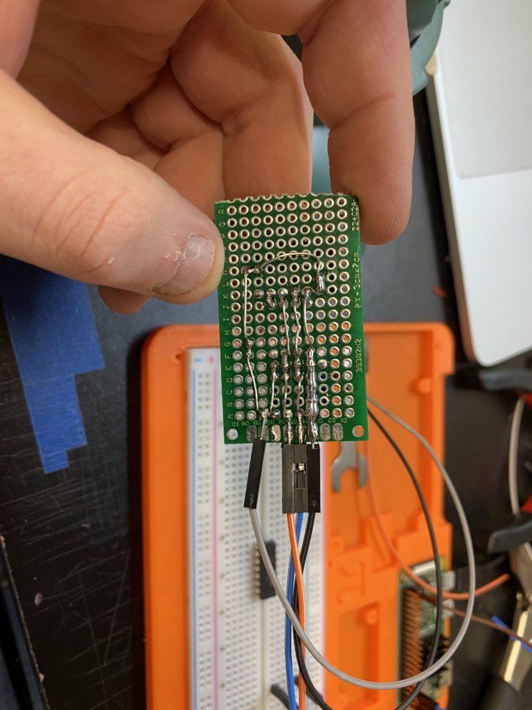
I started out using an RJ11 cable soldered to the board but it turned out to be very tempermental and not wanting to stay soldered. So for the prototyping phase, I opted to just solder on some breadboard jumpers which worked great.
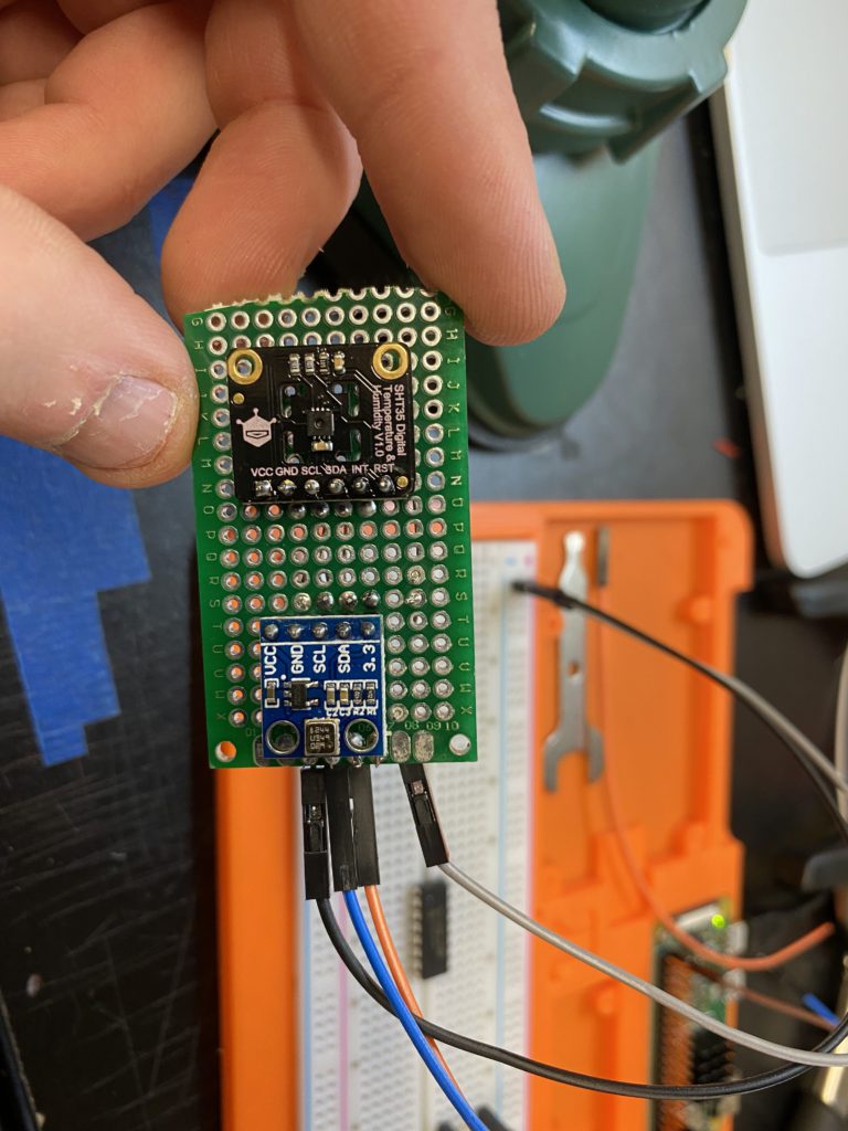
I decided on the orientation I did because the SCL, SDA, and GND pins were both on the same trace. The only difference was the 3.3 and Vcc. I plan on using 3.3v for everything so I did have to accommodate for that.
I decided on ground on one side and vcc on the other, and scl/sda in the middle. It seemed to work pretty well but i’m not sold on that for the final pinout.
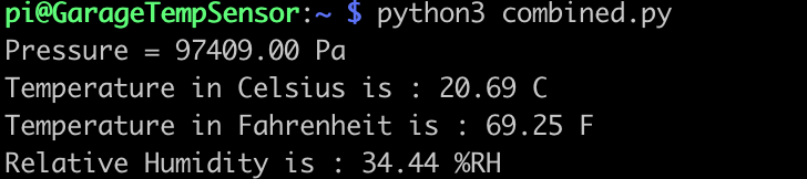
Once I plugged it in, it worked! I was getting output from both sensors
In terms of actual connectivity, I think i’m going to solder an RJ11 socket onto the pcb. This will allow easy replacement/removal of the sensor without having to fish a cable again. It will also make soldering easier.
So now the next step will be to start building a PCB design. I still need to prototype boards for soil/moisture as well as the main pcb, so I’ll probably wait to actually submit and order those until later.